This article shows how to use the timer/counter built into the ATmega328P microcontroller of the Arduino Uno to count external pulses (events). A short introduction to the timer/counter is included in the article Arduino – Timer.
In this example, the actuations of a pushbutton are to be counted. The current counter value is read out periodically and, if it has changed, output to the serial monitor. Purely for control purposes, a LED is connected to the counter input of the microcontroller.
The timer/counter counts the pulses without any software support, i.e. without instructions in loop() and also without interrupt handler. The program only has to initialize the timer/counter and read the counter value if needed.
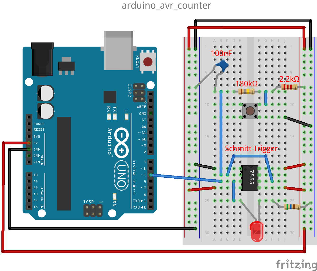
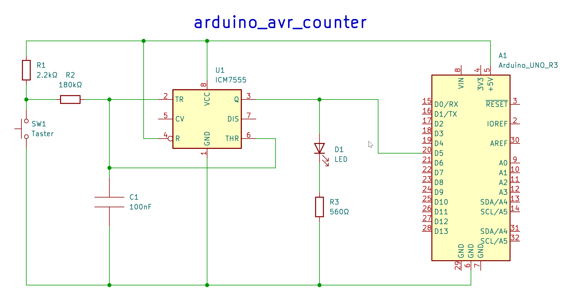
The pushbutton must be debounced in hardware so that the keystrokes are counted correctly. This is done by the left and middle part in the schematic. R1/R2 and C1 provide the debouncing as RC lowpass, while the timer ICM7555 is used here only as Schmitt trigger (I used this one, because it was available in my tinkering box). Of course any device with Schmitt trigger input can be used here (e.g. 74HC14). [Gemarn articles about debouncing, Schmitt-Trigger and 74HC14]
According to the data sheet of the ICM7555 the two threshold voltages of the trigger (TR) and reset (R) inputs are 1/3 and 2/3 of the supply voltage respectively. For a 5V supply these are 1.67V and 3.33V. The following calculation of the resistors R1 and R2 assumes a capacitance C1 of 100nF and a maximum bounce time of 20ms. [Fomulas are taken from here (German)]
R2 = -BouncingTime / (C1 * ln (ThresholdVoltage / SupplyVoltage))
R2 = -0.02 / (10-7 * (ln (1.67 / 5)) = 182’380Ω -> 180kΩ
R1 + R2 = -BouncingTime / (C1 * ln(1 – (ThresholdVoltage / SupplyVoltage)))
R1 + R2 = -0.02 / (10-7 * (ln (1 – (3.33 / 5))) = 182’380Ω -> R1 = 2.2kΩ
Bemerkungen:
- With the assumed threshold voltages of 1.67V and 3.33V (1/3 and 2/3) we would actually get:
R1 + R2 = R2 -> R2 = 182kΩ and R1 = 0kΩ.
But this would mean short circuit when the push button is pressed. So I toke 2.2kΩ for R1. - If another device is used as Schmitt trigger or a push button with longer bounce time, the resistors R1 and R2, and/or the capacitor C1 must be adapted to the threshold voltages of the Schmitt trigger and the bounce time of the push button.
The program (sketch) (https://github.com/schaeren/micro_controller/tree/master/arduino_avr/c/arduino_avr_counter):
#include "Arduino.h"

unsigned long gCount = 0;

void initCounter1() {
    // Diable all interrupts (temporarily)
    noInterrupts();

    // Timer/Counter Control Register A of timer/counter 1
    TCCR1A = 0; // mode = Normal, i.e. WGM11..WGM10 = 00 (Waveform Generation Mode)
                // outputs OC1A and OC1B are disconnected
    // Timer/Counter Control Register B of timer/counter 1
    TCCR1B = 0; // mode = Normal, i.e. WGM13..WGM12 = 00
    TCCR1B |= 1 << CS12 | 1 << CS11 | 1 << CS10; // no prescaler, use external clock, rising edge
    // Timer/Counter value register of timer/counter 1
    TCNT1 = 0; // set start value for counter

    // Enable interrupts again
    interrupts();
}

void setup() {
    Serial.begin(115200);
    initCounter1();
}

void loop() {
    unsigned int count = TCNT1;
    if (gCount < count) {
        gCount = count;
        Serial.println(gCount);
    }
    delay(10);
}
setup() / initCounter1()
Initializes the timer/counter 1 (16-bit) as counter, without prescaler, the positive edges (“0″->”1”) of the pulses at input T1 (PD5) are counted. The counter (register TCNT1) is initialized to 0.
loop()
The loop checks every 10ms if the counter value (register TCNT1) has changed, if so it is output to the serial monitor.