This article shows how to use the internal timers/counters of an Arduino Uno in C/C++ to trigger periodic interrupts. Two different timers, one in normal mode, the other in CTC mode, let two LEDs flashing.
Einführung
Timers/counters can be used for, among other things:
- Measuring times
For this purpose the timer/counter is fed with a regular clock, e.g. with the system clock of the microcontroller. The clock periods are then counted for time measurement. - Periodical execution of functions
For this the timer/counter is fed with a regular clock, the clock frequency determines how often the desired functions are executed by the timer/counter interrupt handler. - Counting of external (binary) events (level changes at an input)
For this the timer/counter is fed with the external events. These may have to be prepared by electronic circuits in such a way that each event corresponds to a pulse: one “0”->”1″ and one “1”->”0″ transition each. The input clock can be regular or irregular.
For information on how to use the Timer/Counter in counter mode see the article Arduino – Counter.
If necessary, the clock frequency can be reduced by a programmable so-called prescaler in the ratio 8:1, 32:1, 64:1, 128:1, 256:1 or 1024:1. e.g. with a 256:1 prescaler the frequency is devided by 256.
The microcontroller ATmega328P of the Arduino Uno has three independent internal timers/counters:
- Timer0 has an 8-bit counter, i.e. it can count from 0..255, then it starts again at 0.
- Timer1 has a 16-bit counter, i.e. it can count from 0..65’535, then it starts again at 0.
- Timer2 has an 8-bit counter, i.e. it can count from 0..255, then it starts again at 0.
However, it is important:
- Timer0 is used for the predefined functions
delay(),millis(),micros(). - Timer1 is used by the Servo library or a similar one, i.e. if the program contains e.g.
#include <Servo.h>or similar. - Timer2 is used by the Tone library or a similar one, i.e. if the program contains e.g.
#include <Tone.h>or similar.
If one of the above functions or libraries is used, the corresponding timer/counter should not be used.
Each timer/counter can be operated in one of four modes (note: the n in the following register names is either 0, 1 or 2 according to the timer/counter used):
- Normal Mode
The timer/counter counts up (register TCNTn). When reaching the maximum value (255 or 65565) an overflow occurs and the counter starts again at zero. An interrupt can be triggered at the overflow -> Timer Overflow Interrupt. The current counter value (register TCNTn) can be overwritten at any time. Usually it is reinitialized to a predefined value by the interrupt handler. - Clear Timer on Compare Match (CTC) Mode
The timer/counter counts up (register TCNTn) until a programmed compare value (register OCRnA) is reached, then it starts again at zero. At the same time, an interrupt can be triggered -> Timer/Counter n Compare Match A Interrupt. The comparison value (register OCRnA) remains unchanged, but can be changed at any time (e.g. by the interrupt handler). Note: If OCRnA is set to a value smaller than the current counter value TCNTn, the counter must first overflow before it can reach the OCRnA value. - Fast PWM Mode
This mode will not be discussed here. - Phase Correct PWM Mode
This mode will not be discussed here.
For more information about timer/counter check the datasheet of ATmega328P.
For the timer/counter interrupts, the interrupt handlers can be registered similar to what is explained in the article Arduino – Interrupt.
Example
The following example uses two timers/counters to make two LEDs blink
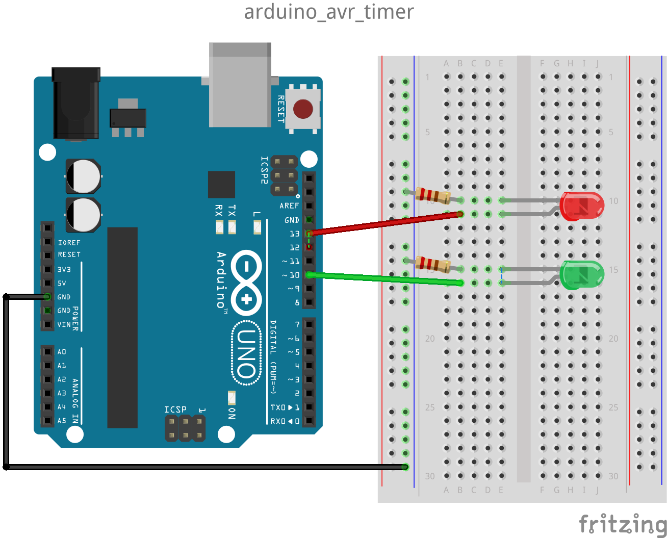
The green LED is controlled by Timer1 and should blink with exactly 0.5 Hz (i.e. 1000 ms on / 1000 ms off).
- 16-bit counter
- Initialization:
initTimer1() - Mode: Normal Mode
- The prescaler is initialized to 1024:1, i.e. the input clock (system clock) of 16 MHz is divided by 1024 -> 15’625 Hz
- The counter (register TCNT1) counts from 49911 to 65535, then triggers an Overflow Interrupt, whose interrupt handler sets the counter back to 49911. At the same time the pin which controls the green LED is inverted.
The number 49911 is calculated from 65535 + 1 – 15’625.
The red LED is controlled by Timer2 and should blink with 0.5 Hz.
- 8-bit counter
- Initialization:
initTimer2() - Mode: CTC Mode (CTC = Clear Timer on Compare Match)
- The prescaler is initialized to 1024:1, i.e. the input clock (system clock) of 16 MHz is divided by 1024 -> 15’625 Hz
- The comparison value required for the CTC mode (register OCR2A) is initialized to 155.
- So the counter (register TCNT2) counts each time from 0 to 155 and then starts again at 0. At the same time the Timer/Counter Compare Match A Interrupt is triggered, whose interrupt handler inverts the pin controlling the red LED at every hundredth call.
Why is the LED inverted only at every hundredth interrupt? Because the timer/counter 2 has only an 8-bit counter, and therefor the input frequency (system clock) of 16 MHz with the maximum prescaler value of 1024:1 and a maximum 8-bit comparison value of 255 cannot be divided down to 0.5 Hz:
min-freq = 16’000’000 / 1024 / (255 + 1) = 61.035 Hz.
Therefore in this example an interrupt frequency of 100 Hz is aimed at as exactly as possible. This is best achieved with the comparison value (register OCR2A) of 155:
irq-freq = 16’000’000 / 1024 / (155 + 1) = 100.16 Hz -> LED frequency = 0.5008 Hz
That means, while the green LED flashes with exactly 0.5 Hz, the red LED is a bit too fast with 0.5008 HZ, which becomes visible after 1-2 minutes.
The program / sketch (https://github.com/schaeren/micro_controller/tree/master/arduino_avr/c/arduino_avr_timer):
#include "Arduino.h"

const int greenLedPin = 10; // green LED
const int redLedPin = 13;   // red LED (and onboard LED)

// Start value for timer1, i.e timer/counter runs from this value up to 2^16-1 and then
// restarts with 0 (=overflow). Each overflow creates a Timer Overflow Interrupt. The
// interrupt handler will set the timer/counter again to this value.
//   65535 = 2^16 - 1  is the max value for timer/counter 1
//   16000000 is the CPU clock frequency (16 MHz)
//   1024 is the prescaler value set for timer/counter 1 (see initTimer1())
//
// timer-irq-freq = system-clock-freq / (prescaler * (65535 - timer2CompareValue + 1))
// => timer2CompareValue = 65535 + 1 - (system-clock-frq / (precaler * timer-irq-freq))
//
const unsigned int timer1StartValue = 65535 + 1 - (16000000 / (1024 * 1)); // = 49911

// Compare value for timer2, i.e timer/counter runs from 0 up to this value and then
// restarts with 0. Each time this value is reached a Timer Compare Match Interrupt is
// created.
//   16000000 is the CPU clock frequency (16 MHz)
//   100 divisor to get 10ms intervals
//   1024 is the prescaler value set for timer/counter 1 (see initTimer1())
//
// timer-irq-freq = system-clock-freq / (prescaler * (1 + timer2CompareValue))
// => timer2CompareValue = (system-clock-freq / (timer-irq-freq * prescaler)) - 1
// timer-irq-frq = (16000000 / (100 * 1025)) -1 = 155.25 -> 155
// timer-irq-freq = 16000000 / (1024 * (1 + 155)) = 100.160 Hz -> period = 9.984 ms
//
const unsigned short timer2CompareValue = (16000000 / 100 / 1024) - 1; // = 155

unsigned int timer2CycleCounter = 0;

void initTimer1() {
    // diable all interrupts (temporarily)
    noInterrupts();

    // Timer/Counter Control Register A of timer1
    TCCR1A = 0; // mode = Normal, i.e. WGM11..WGM10 = 00 (Waveform Generation Mode)
                // outputs OC1A and OC1B are disconnected
    // Timer/Counter Control Register B of timer1
    TCCR1B = 0; // mode = normal, i.e. WGM13..WGM12 = 00 (Waveform Generation Mode)
    TCCR1B |= 1 << CS12 | 1 << CS10; // Prescaler = 1024, i.e. CS12..CS10 = 101
    // Timer/Counter value register of timer1
    TCNT1 = timer1StartValue; // set start value for timer/counter 1
    // Timer/Counter Interrupt Mask Register of timer1
    TIMSK1 |= 1 << TOIE1; // enable Timer Overflow Interrupt

    // Enable interrupts again
    interrupts();
}

void initTimer2() {
    // diable all interrupts (temporarily)
    noInterrupts();

    // Timer/Counter Control Register A of timer2
    TCCR2A = 0;
    TCCR2A |= 1 << WGM21; // mode = CTC, i.e. WGM21..WGM20 = 10 (Waveform Generation Mode)
                          // CTC: Clear Timer on Compare Match
                          // outputs OC2A and OC2B are disconnected
    // Timer/Counter Control Register B of timer2
    TCCR2B = 0;  // mode = CTC, i.e. WGM22 = 0 (Waveform Generation Mode)
    TCCR2B |= 1 << CS22 | 1 << CS21 | 1 >> CS20; // Prescaler = 1024, i.e. CS22..CS20 = 111
    // Output Compare Register A for timer2
    OCR2A = timer2CompareValue;
    // Timer/Counter value register of timer2
    TCNT2 = 0; // set start value for timer/counter 2
    // Timer/Counter Interrupt Mask Register of timer2
    TIMSK2 |= 1 << OCIE2A; // enable Timer Overflow Interrupt

    // Enable interrupts again
    interrupts();
}

ISR(TIMER1_OVF_vect)
{
    TCNT1 = timer1StartValue;
    Serial.print("Timer1: ");
    Serial.println(millis());
    digitalWrite(greenLedPin, digitalRead(greenLedPin) ^ 1);
}

ISR(TIMER2_COMPA_vect) {
    if (++timer2CycleCounter == 100) {
        timer2CycleCounter = 0;
        Serial.print("Timer2: ");
        Serial.println(millis());
        digitalWrite(redLedPin, digitalRead(redLedPin) ^ 1);
    }
}

void setup() {
    pinMode(greenLedPin, OUTPUT);
    pinMode(redLedPin, OUTPUT);
    Serial.begin(115200);
    Serial.print("timer1StartValue = ");
    Serial.println(timer1StartValue);
    Serial.print("timer2CompareValue = ");
    Serial.println(timer2CompareValue);
    initTimer1();
    initTimer2();
}

void loop() {
}
Remarks:
- The green LED does not blink exactly with 0.5 Hz, but a bit slower, because some microseconds pass between rising the Overflow Interrupt and resetting the counter to 49911 in the interrupt handler
ISR(TIMER1_OVF_vect)(line 78). However, this delay is negligible compared to the rounding error in Timer2, which is in the range of about 3.2ms per blink period (2 s).
Therefore it is important that the counter reset (TCNT1 = timer1StartValue;) happens at the very beginning of the interrupt handler if possible. If e.g. this statement is called after theSerial.print..()statements, the degradation will be visible in the print outputs after some cycles, because the twoSerial.print..()take significant time. - Since the red LED is connected to pin 13, the yellow on-board LED of the Arduino Uno driven by the same pin will flash, too.